Summary
The vortex flowmeter is used in the flow measurement of the fluid in the industrial pipe line, such as gas, liquid, steam, etc..Its characteristics are less pressure loss, no movable mechanism in the meter. This flow meter adopts piezoelectric sensor, has high reliability, works with in -20Ąæ to + 250Ąæ. There are standard analogue signal (4-20mA) or pulse signal outputs, it is easy to be used together with digital systems, such as computer, etc.
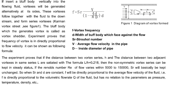
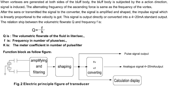
Measure Principle


Technical Parameter
Table 1
Standard adopted | Q/YH C0401-2001 JB/6807-93 | |
Medium | Gas, liquid. steam | |
Diameter | Wafer Type | 15,25, 30, 40, 50, 65,80, 100,125,150 |
Flange connection type | 200 | |
Flow Measuring scope | Normal flow velocity range | Gas 5-50m/s Liquid 0.5-7m/s |
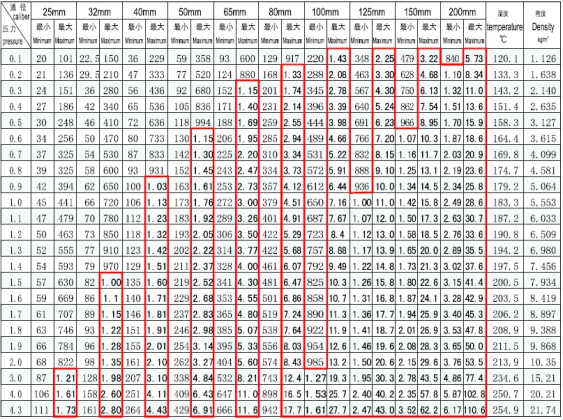
Normal flowrate range | Liquid, gas, steam type flow range refer to table 2,3 as follows | |
Accuracy | Liquid ĄĀ1ĢĨĢŽ or gas ĄĀ1.5ĢĨ | |
Medium temperature | Routine temperature -25Ąæ-100Ąæ high temperature -25Ąæ-150Ąæ or -25Ąæ-250Ąæ | |
Working pressure | 1.6Mpa; 2.5Mpa, 4.0Mpa(Supply as orderĄŊs requirement) | |
Output signal(signal cable connection is M20x1.5) | Pulse voltage Output signal | High level 8-10V Low level 0.7-1.3V (Ex-proof version: High level4-5V, Low level 0.7-1.3V) |
Duty ratio of pulse is about 50%, transmission distance 100 meters. | ||
Standard Current output signal | Allowable external load resistance less than 600Ķļ(24VDC) Transmission distance is 3000 meters | |
Working environmental condition | Temperature: -25Ąæ-+55Ąæ humidity:5-90ĢĨ RH50Ąæ | |
Material | Meter body:1Cr18Ni9Ti Converter housing: AL-allog | |
Power supply | 24V DCĄĀ10ĢĨ; Or dual lithium battery 3.6 V 7.5 Ah | |
Protection grade | IP65 | |
Requirement of straight connecting pipe on both sides of the meter | UpstreamĄÝ15-35 DN ; DownstreamĄÝ10 DN | |
Liquid & Gas Flow Range at Working Condition
Table 2
DN (mm) | 15 | 20 | 25 | 32 | 40 | 50 | 65 | 80 | 100 | 125 | 150 | 200 | 250 | 300 |
Liquid (m3/h) | 0.3-3 | 0.5-5 | 1.2-12 | 1.5-15 | 2.2-22 | 4-40 | 6-60 | 9-90 | 14-140 | 22-220 | 35-350 | 65-650 | 120-1200 | 180-1800 |
Gas (m3/h) | 5-30 | 5.5-56 | 10.2-80 | 15-150 | 22-220 | 35-350 | 60-600 | 90-900 | 140-1400 | 220-2200 | 300-3000 | 550-5500 | 1100-11000 | 1500-15000 |
Flow Range of Saturated Steam
Table 3

Note: Unit in red frame data is t/h Rest is kg/h. Unit of pressure: Mpa
Flow Range of Liquid(gas,steam) for insert type
DN(mm) | Liquid(m3/h) | Gas(m3/h) | DN(mm) | Liquid(m3/h) | Gas(m3/h) | ||||
Min. | Max. | Min. | Max. | Min. | Max. | Min. | Max. | ||
200 | 85 | 570 | 560 | 4530 | 900 | 1145 | 11450 | 11450 | 91605 |
250 | 88 | 885 | 880 | 7070 | 1000 | 1410 | 14140 | 14135 | 113095 |
300 | 125 | 1275 | 1270 | 10180 | 1100 | 1710 | 17110 | 17100 | 136840 |
350 | 170 | 1735 | 1730 | 13860 | 1200 | 2035 | 20360 | 20230 | 162850 |
400 | 225 | 2265 | 2260 | 18100 | 1300 | 2385 | 23895 | 23890 | 191125 |
450 | 286 | 2870 | 2860 | 22905 | 1400 | 2770 | 27710 | 27705 | 221660 |
500 | 350 | 3540 | 3530 | 28275 | 1500 | 3170 | 31800 | 31700 | 254455 |
600 | 505 | 5090 | 5085 | 40715 | 1600 | 3610 | 36200 | 36105 | 289510 |
700 | 690 | 6930 | 6925 | 55420 | 1800 | 4580 | 45850 | 45750 | 366410 |
800 | 900 | 9050 | 9045 | 72380 | 2000 | 5650 | 56550 | 56545 | 452365 |
Construction and Size
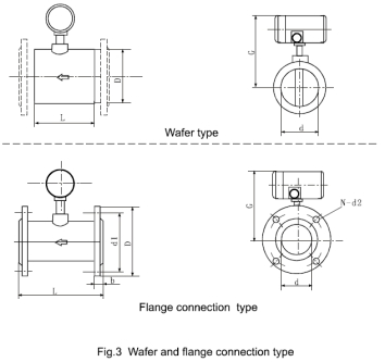
ĄôThis series has two kinds of connection forms and external dimensions
▶Wafer type
Used for vortex flowmeter of fully filled type in DN15-100 ranges,see Fig3 and Table 5.
▶Flange type
Used for vortex flowmeter of fully filled type in DN125-200 ranges,see Fig3 and Table 5.

Dimensions
Table 5
Type | Nominal Caliber | Pressure Grade | L mm | G | D mm | d1 mm |
N-d2 | d mm | b mm | Weight Kg | |
Normal temperature | High Temperature | ||||||||||
Wafer Type | 15(20) | 4.0 | 66 | 280 | 500 | 65 | ĄŠ | ĄŠ | 15ĢĻ20ĢĐ | 15 | 7.5 |
25 | 4.0 | 66 | 280 | 500 | 65 | ĄŠ | ĄŠ | 25 | 25 | 7 | |
32 | 4.0 | 66 | 285 | 505 | 72 | ĄŠ | ĄŠ | 32 | 32 | 10 | |
40 | 4.0 | 70 | 290 | 510 | 80 | ĄŠ | ĄŠ | 40 | 40 | 11 | |
50 | 4.0 | 85 | 295 | 515 | 90 | ĄŠ | ĄŠ | 50 | 50 | 12.5 | |
65 | 2.5 | 98 | 310 | 530 | 105 | ĄŠ | ĄŠ | 65 | 65 | 17 | |
80 | 2.5 | 110 | 320 | 540 | 120 | ĄŠ | ĄŠ | 80 | 80 | 20 | |
100 | 2.5 | 110 | 330 | 550 | 150 | ĄŠ | ĄŠ | 100 | 100 | 27 | |
125 | 1.6 | 115 | 340 | 560 | 164 | ĄŠ | ĄŠ | 125 | 125 | 30 | |
150 | 1.6 | 130 | 350 | 570 | 188 | ĄŠ | ĄŠ | 150 | 150 | 35 | |
Flange type | 125 | 1.6 | 250 | 323 | 545 | 245 | 210 | 8-Ķĩ18 | 125 | 26 | 22 |
150 | 1.6 | 300 | 335 | 555 | 280 | 240 | 8-Ķĩ23 | 150 | 28 | 24 | |
200 | 1.6 | 320 | 370 | 590 | 335 | 295 | 12-Ķĩ23 | 200 | 30 | 31 | |
250 | 1.6 | 320 | 400 | 620 | 405 | 355 | 12-Ķĩ25 | 250 | 32 | 40 | |
300 | 1.6 | 320 | 420 | 640 | 460 | 410 | 12-Ķĩ25 | 300 | 32 | 48 | |
Model Selection
Model chart | Describing | ||||||||||
LUDC | Basic model of stress vortex transmitter | ||||||||||
Connection type | -1 | Flange type (DN15~300) | |||||||||
-2 | Wafer type (DN15-150) | ||||||||||
-3 | Insertion type (DN200-2000) | ||||||||||
Test medium | 2 | Liquid | |||||||||
3 | Gas | ||||||||||
4 | Saturated steam | ||||||||||
4G | Overheated steam | ||||||||||
5 | Hot water | ||||||||||
Nominal diameter | -xxx | Reference to DN code table | |||||||||
Output signal | -0 | No signal output | |||||||||
-3 | Three-wire pulse output | ||||||||||
-4 | Two-wire 4ĄŦ20mA current output | ||||||||||
Indicate type | N | No indicator | |||||||||
B | Dual row LCD (instantaneous and cumulant flow ) | ||||||||||
Power supply | X | 12V DC (only equip with three-wire pulse output) | |||||||||
Y | 24V DC | ||||||||||
Z | Battery power supply(only for LCD) | ||||||||||
Body material | -C | OCr18Ni12Mo2Ti(316) | |||||||||
-D | 1Cr18Ni9Ti(304) | ||||||||||
Pressure type | 1 | 1.6Mpa(DNĄÝ125) | |||||||||
2 | 2.5Mpa(DN65~100) | ||||||||||
3 | 4.0Mpa(DN15~50) | ||||||||||
Explosion-proof performance | -N | No | |||||||||
-Bi | Intrinsically safe explosion-proof | ||||||||||
-Bd | Flame-proof type | ||||||||||

Code and Diameter
DN | 15 | 20 | 25 | 32 | 40 | 50 | 65 | 80 | 100 | 125 | 150 | 200 | 250 | 300 | ... | 1000 | ... | 2000 |
Code | 001 | 0012 | 002 | 003 | 004 | 005 | 006 | 008 | 010 | 012 | 015 | 020 | 025 | 030 | ... | 100 | ... | 200 |
Changzhou Voha Instrument Co., Ltd.


