1. SPECIFICATION
Performance
Repeatability: Àâ0.2%
Accuracy: Standard:Àâ1.5% of reading;
Optional:Àâ1.5% of reading or Àâ0.75% of reading
Wetted Components
Housing: Standard:Tungsten Carbide;
Optional:304,316SS
Bearings and Shaft: ABS(Corrosion Resist) or Aluminium-Alloy
Rotor: ABS(Corrosion Resist) or Aluminium-Alloy
Retaining Rings: 304 Stainless Steel
Output Signal:(Where applicable)
Sensor: Pulse signal(Low level:ÀÉ0.8V,High levelÀï8V)
Transmitter: 4 to 20 mA DC current signal
Signal Transmission Distance:ÀÉ1,000m
Electric Connections:
Basic Type: Hausman connector or Three-core cable
Explosion Proof Type: ISO M20Àê1.5 Female
Explosion Proof Level:
Standard: None ;
Optional: ExdIIBT6
Protection Level: IP65
2. OPERATION CONDITIONS
Ambient:
Temperature: -10ÀÌ to +55ÀÌ
Pressure: 86 to 106KPa
Relative Humidity: 5% to 90%
Power Supply:
Sensor: +12V DC(Optional:+24V DC)
Transmitter: +24V DC
Field Display Type B: Integral 3.2V Lithium Battery
Field Display Type C: +24V DC
Fluid Temperature and Pressure:
Temperature: -30ÀÌ to +80ÀÌ
Pressure: Fluid pressure should be limited according to flange rating.
Measurable Flow Rate Range and Pressure Level:(See table 1)
Table 1.Measurable Flow Range and Pressure Rating
Nominal Diameter | Model | Standard Flow Range | Extended Flow Range | Standard Pressure Rating | Customized Pressure Rating | Installation Type | ||
(mm) | LWQ- | (m3/h) | (m3/h) | (MPa) | (MPa)-Flange fitting | Flange(thread) | ||
DN25 | LWQ-25 | S | 2.5~25 | K | 4~40 | 1.6 | 2.5,4.0 | Flange(thread) |
DN40 | LWQ-40 | S | 5~50 | K | 6~60 | 1.6 | 2.5,4.0 | Flange |
DN50 | LWQ-50 | S1 | 6~65 | K1 | 5~70 | 1.6 | 2.5,4.0 | Flange |
S2 | 10~100 | K2 | 8~100 | |||||
DN65 | LWQ-65 | S | 15~200 | K | 10~200 | 1.6 | 2.5,4.0 | Flange |
DN80 | LWQ-80 | S1 | 13~250 | K | 10~160 | 1.6 | 2.5,4.0 | Flange |
S2 | 20~400 | |||||||
DN100 | LWQ-100 | S1 | 20~400 | K | 13~250 | 1.6 | 2.5 | Flange |
S2 | 32~650 | |||||||
DN125 | LWQ-125 | S | 25~700 | K | 20~800 | 1.6 | 2.5 | Flange |
DN150 | LWQ-150 | S1 | 32~650 | K | 80~1600 | 1.6 | 2.5 | Flange |
S2 | 50~1000 | |||||||
DN200 | LWQ-200 | S1 | 80~1600 | K | 50~1000 | 1.6 |
| Flange |
S2 | 130~2500 | |||||||
DN250 | LWQ-250 | S1 | 130~2500 | K | 80~1600 | 1.6 |
| Flange |
S2 | 200~4000 | |||||||
DN300 | LWQ-300 | S | 200~4000 | K1 | 130~2500 | 1.6 |
| Flange |
K2 | 320~6500 | |||||||
3. MODEL AND SELECTION
Performance
4.1 Turbine Flow Sensor/Transmitter
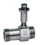
LWQ-C Type Sensor:12 to 24V DC Power Supply;Pulse Output
LWQ-F Type Transmitter:24V DC Power Supply;2-wire,4 to 20 mA Output
Basic Type(Without Explosion Proof) and Explosion Proof Type are optional for LWQ-C and LWQ-F.


Basic Type Explosion Proof Type
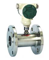
4.2 Intelligent Integrated Turbine Flow Meter
˦4 digital instantaneous flow display
˦8 digital totalizator flow display(Resettable)
˦With Explosion Proof(Level:ExdIIBT6)
˦3-Point Correction and Non-linearity Compensation on K-Factor
Note:The K-Factor represents the number of output pulse transmitted per cubic meter(Optional:Liter and Gallons) of Fluid passing through the turbine meter.Each turbine has a unique K-Factor.However,turbine meters are not functionally consistent throughout the full flow range of the meter.Therefore,correction and non-linearity compensation on K-Factor can enhance accuracy.
LWQ-Y Type:Powered with 3.2V 10AH lithium battery(Battery lifeȃ4 years);no output
LWQ-B Type:24V DC Power Supply;2-wire 4~20mA Output(Optional:RS485 or HART)
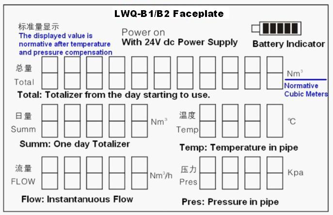
LWQ-B1/B2 Type (With temperature and pressure compensation): 24V DC Power Supply

Model Selection(See Table 2)
Table 2.Model Selection Guidance
Model | Specification(SFR:Standard Flow Range) | ||||||||
LWQ | À¾ | -À¾ | /À¾ | /À¾ | /À¾ | /À¾ | /À¾ | /À¾ | |
Type | C |
|
|
|
|
|
|
| Sensor type:+12V or 24V power supply, |
F | Transmitter type:+24V power supply,two-wire 4~20mA current output | ||||||||
Y | Lithium battery power supply,on-site display without signal output | ||||||||
B | +24V power supply,on-site display with | ||||||||
B1 | With temperature and pressure compensation, | ||||||||
B2 | With temperature and pressure compensation, | ||||||||
Nominal Diameter(mm) | 25 | DN25mm | |||||||
40 | DN40mm | ||||||||
50 | DN50mm | ||||||||
65 | DN65mm | ||||||||
80 | DN80mm | ||||||||
100 | DN100mm | ||||||||
125 | DN125mm | ||||||||
150 | DN150mm | ||||||||
200 | DN200mm | ||||||||
250 | DN250mm | ||||||||
300 | DN300mm | ||||||||
Flow Range | K | Extended flow range,refer to Table 1 | |||||||
S | Standard flow range,refer to Table 1 | ||||||||
Body Material | P | 304SS | |||||||
L | Cast aluminium | ||||||||
Core Material | A | Anti-corrosion ABS | |||||||
L | Aluminium-alloy | ||||||||
Explosion Class | O | Blank:without explosion proof | |||||||
E1 | Exia II CT4 | ||||||||
E2 | Exd II BT6 | ||||||||
Pressure Level | S | Standard | |||||||
H(x) | High pressure:refer to Table1 | ||||||||
Accuracy Class | S | Standard class:1.5 | |||||||
G(x) | Customized class:1.0,0.75 | ||||||||
Changzhou Voha Instrument Co., Ltd.


